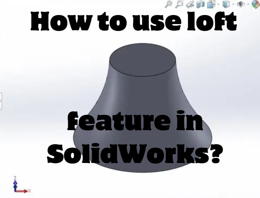
Learn how to use the loft feature in SolidWorks to accelerate your designs.
Create a loft part with SolidWorks
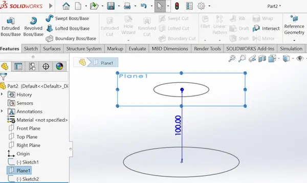
In order to complete the loft function we need two profiles ( sketches) linked by two guide curves.
First create the two sketches on two parallel plans, here you will need to create another plan, make it parallel and have a predetermined distance from a chosen plane.
Then create the guide curves sketches on a Perpendicular plane to the other two.
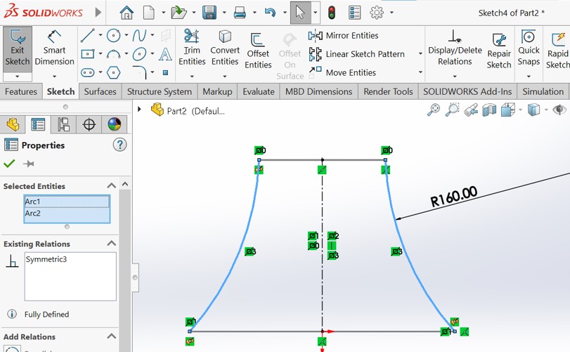
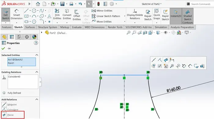
Just make sure that the points on each curve are in pierce relation with each profile.
This important so we can have connected surfaces later on without any gaps or errors.
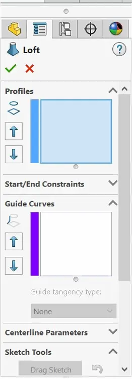
Now go to features -> Lofted Boss/Base, select the first two sketches as profiles then select the lines asa guide curves and press enter.
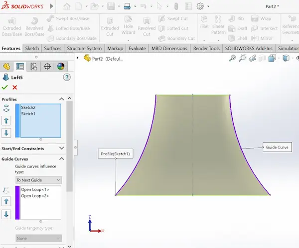
That’s it you have created a lofted body with the loft feature.
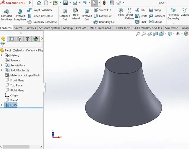
If you want to create an hollow part with the loft feature, scroll down to thin feature and choose the desired wall thickness and it’s direction.
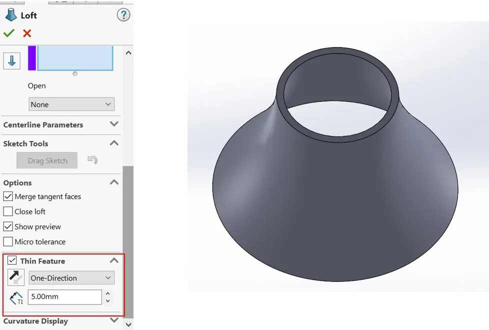
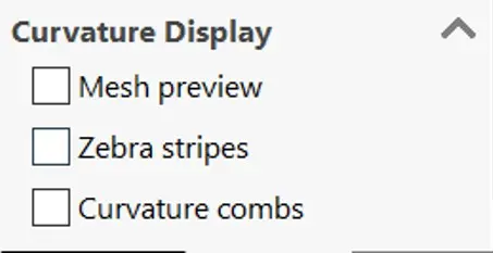
More advanced display options
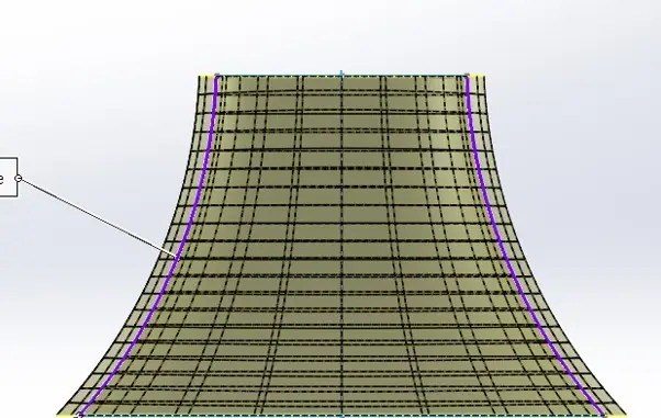
In the bottom of the loft window, you can find three display options : Mesh preview, Zebra stripes and curvature combs.
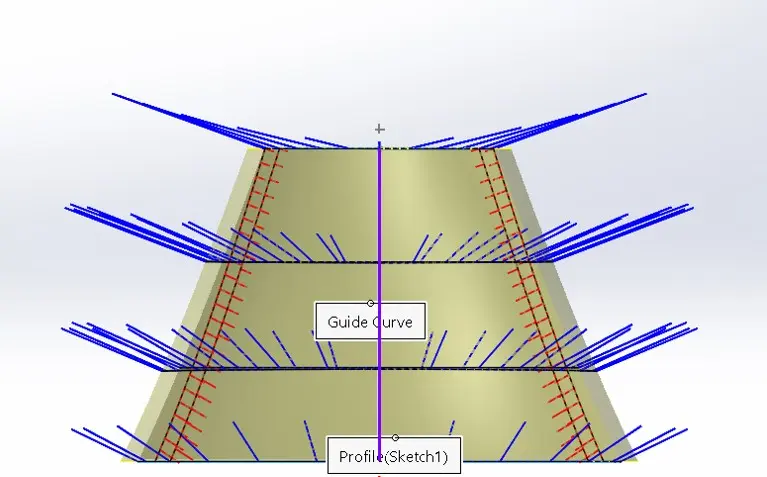
- Curvature combs: Curvature combs provide visual enhancement of the slope and curvature of most sketch entities in part, assembly, and drawing documents.
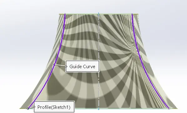
- Zebra stripes: Zebra stripes allow you to see small changes in a surface that may be hard to see with a standard display. Zebra stripes simulate the reflection of long strips of light on a very shiny surface.
- With zebra stripes, you can easily see wrinkles or defects in a surface, and you can verify that two adjacent faces are in contact, are tangent, or have continuous curvature.
- Mesh preview: display the lines of the connected data points that forms the model.